
L&TD
LOGGING & TESTING DIVISION
Sản phẩm dịch vụ
RTTS Safety Joint
|
RTTS Safety Joint The RTTS safety joint is an optional emergency backoff device. The safety joint releases the workstring and tools above the packer if the packer becomes stuck during operations.The design of the RTTS safety joint makes unintentional operation difficult. Features and Benefits • Positive sequence of operation helps prevent premature release. • Tools above it can be retrieved when string is stuck Operation The RTTS safety joint is run immediately above the RTTS packer so that the greatest number of tools above the packer can be removed.Before the safety joint can be used, a tension sleeve located on the bottom of the lug mandrel must first be parted by pulling up on the workstring.After the tension sleeve has parted, the safety joint is released by right-hand torque while the workstring is rotated a specified number of cycles.
RTTS Safety Joint
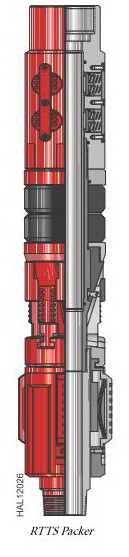
These are the most common sizes. Other sizes may be available. **The values of tensile, burst, and collapse strength are calculated with new tool conditions, Lame’s formula for burst and collapse strength, and stress area calculations for tensile strength. These ratings are guidelines only. For more information, consult your local Halliburton representative. RTTS Packer The RTTS packer is a full-opening, hookwall packer used for testing, treating, and squeeze cementing operations. In most cases, the tool runs with a circulating valve assembly.The packer body includes a J-slot mechanism, mech anical slips, packer elements, and hydraulic slips. Large, heavy-duty slips in the hydraulic holddown mechanism help prevent the tool from being pumped up the hole. Drag springs operate the J-slot mechanism on ≤ 3 1/2-in. (88.9-mm) packer bodies, while larger packer sizes ≥ 4-in. (101.6 mm) use drag blocks. Automatic J-slot sleeves are standard equipment on all packer bodies. The circulating valve, if used, is a locked-open/locked-closed type that serves as both a circulating valve and bypass. The valve automatically locks in the closed position when the packer sets. During testing or squeezing operations, the lock prevents the valve from being pumped open. A straight J-slot in the locked-open position matches with a straightJ-slot (optional) in the packer body. This combination eliminates the need to turn the tubing to close the circulating valve or reset the packer after the tubing has been displaced with cement. Features and Benefits • The full-opening design of the packer mandrel bore allows large volumes of fluid to pump through the tool. Tubing-type guns and other wireline tools can be run through the packer. • The packer can be set and relocated as many times as necessary with simple tubing manipulation. • Tungsten carbide slips provide greater holding ability and improved wear resistance in high-strength casing. Pressure through the tubing activates the slips in the hydraulic holddown mechanism. • An optional integral circulating valve locks into open or closed position during squeezing or treating operations, and opens easily to allow circulation above the packer. Operation The tool is run slightly below the desired setting position to set the packer and is then picked up and rotated several turns. If the tool is on the bottom, only a half-turn is actually required. However, in deep or deviated holes, several turns with the rotary may be necessary. To maintain position, theright-hand torque must be held until the mechanical slips on the tool are set and can start taking weight.The pressure must be equalized across the packer to unset it. As the tubing is picked up, the circulating valve remains closed, establishing reverse circulation around the lower end of the packer. The circulating valve is opened for coming out of the hole when the tubing is lowered, rotated to the right, and picked up. RTTS Packer
|

Nhóm Marketing
Compensated Spectral Natural Gamma Ray
|
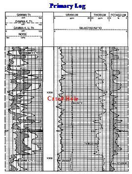 |
| In order to use the latest technique of wireline logging and for more accurate lithology analysis of sedimentary and basement rock from 1997, Vietsovpetro L&TD has been using Halliburton’s CSNG™.
CSNG™ provides highly accurate measurements of potassium, uranium, and thorium by detecting the gamma rays they emit. The concentrations of these elements reveal petrological information to help ensure clean rock is not mistaken for shale or clay. For example: with a standard gamma ray log, high gamma ray counts are frequently interpreted as shale. In the same environment, the CSNG could correctly attribute high gamma ray counts to the presence of uranium or potassium and correctly identify the rock as a potential reservoir. |
|
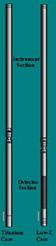
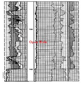
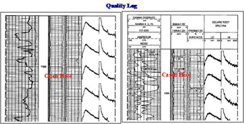
The CSNG measures the entire gamma spectrum, from 0 to 3000 keV, in both open and cased holes, producing both a primary and a quality log in real-time.
|
 |
 |
|
Nhóm Marketing |
DPP&PETROSITE Desktop Petrophysics Software
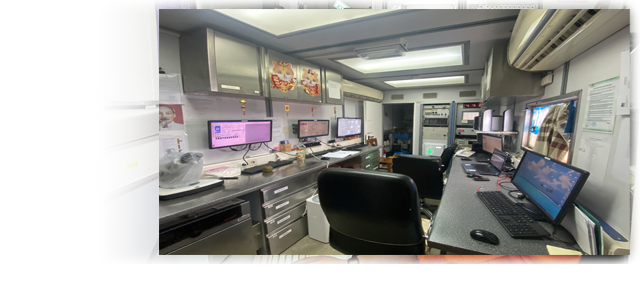
In order to provide the best results from wireline logging data processing/interpretation, from 1997 Vietsovpetro L&TD starting to utilize a full range of processing/interpretation programs. This is Halliburton’s Desktop Petrophysics software and Petrosite software running in a complete system. The system comprises two IBM-RS-6000 servers running in AIX environment with six terminals connected through a LAN and one HP workstation running in Window environment. This is a multi task and multi-user system. 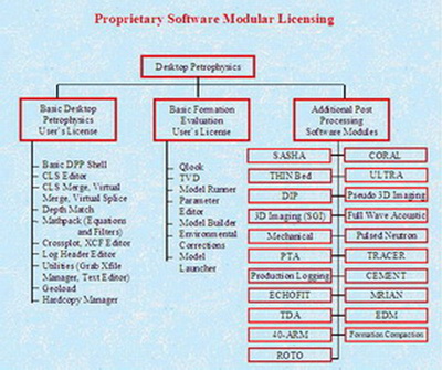 |
| Halliburton’s Desktop Petrophysics (DPP) and Petrosite are integrated software packages that converts, stores, analyzes, and manipulates log data. The Desktop Petrophysics&Petrosite suite of applications allows the user to manage and manipulate log data for further evaluation and interpretation.
The DPP & Petrosite applications run cohesively in a common “desktop” environment under OSF/Motif TM, thus offering a consistent user interface based on the X-Window system.
All DPP& Petrosite applications run from a common CLS database, and use a single messaging system to communicate with one another. |
Offered as a package, but available as individual applications, Desktop Petrophysics&Petrosite provides the tools needed to meet the demand for more in-depth reservoir analysis and evaluation.
The DPP & Petrosite applications are grouped. There are main groups: Basic Desktop Petrophysics, Basic Formation Evaluation Package and Additional Post Processing Software Modules. Each application in the Desktop Petrophysics & Petrosite suite is described briefly below. |
| A- BASIC DESKTOP PETROPHYSICS & PETROSITE PACKAGE
GEOLOAD Converts Log Data between CLS Database format and LIS and LAS formats. Also can output ASCII file and verify LIS. CLS EDITOR View and edit Log Data in CLS Database file in value versus sample depth matrix. Create, delete, rename or copy curves. SCROLLPLOT Interactively display CLS log data on screen, or output as TIFF file. Annotate logs, label/rescale curves, plot special curves (waveform, image, dip arrow, etc.). SPC EDITOR Build/edit a Scroll Plot Control file (.spc) to format plots run from the Scroll Plot program. |
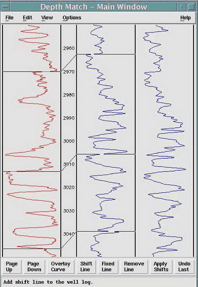 DEPTH MATCH Graphically stretch, compress, or linearly shift curves in CLS Database. DEPTH MATCH Graphically stretch, compress, or linearly shift curves in CLS Database. |
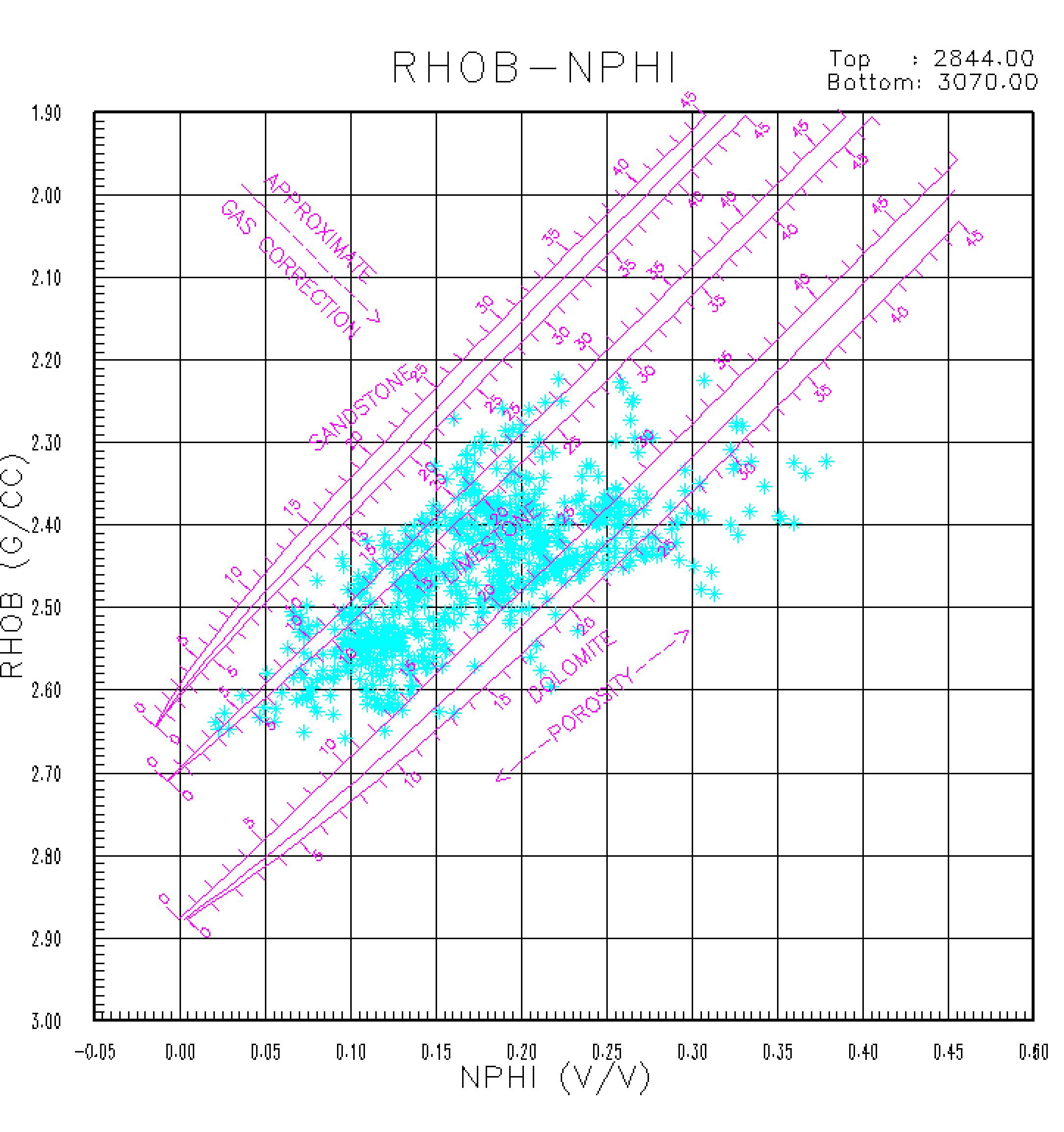
XCF EDITOR Build/edit a Cross Plot Control file (.xcf) to format plots run from the Cross Plot program. |
|
HARDCOPY MANAGER Plot TIFF file of logs, cross plots, and screen dumps on selected plotter. MATHPACK Perform mathematical, logical, filter operations on CLS database curves, and save processing steps as user programs. Display data histogram with statistical calculation. LOG HEADER EDITOR The Log Header Editor program is used to generate API standard log headers to include with plots produced by other Desktop Petrophysics application. You can select from a list of header types that include Open Hole, Cased Hole, and Formation Tester. The Log Header Editor program has the option to read the information stored in the CLS database. The HardCopy Manager program to generate the header plots for the different plotters uses data saved by the program. B- BASIC FORMATION EVALUATION PACKAGE QLOOK is a quicklook to complex reservoir analysis model. Although the program will function with a minimum of one porosity data input, one clay determination data input and one deep resistivity data input; it provides improved results with additional input data. The program determines any 3 mineral combination from a list of 17 available minerals; plus clay; when density-neutron-Pe-resistivity data are available. When sonic travel time is added, the sonic enhances the program’s ability to deal with bad hole or to provide secondary porosity determination or both. The addition of flushing zone resistivity allows for a moveable hydrocarbon plot. QLOOK features several computational options including: selection of desired clay indicators, selection of gamma ray – Vcl transformations, and selection of water saturation models. QLOOK contains a microlog indicated permeability routine that complements the standard computed results if micro-electric data is present. |
|
Model Builder This feature enables anyone with Fortran programming knowledge to develop analysis or other data manipulation programs which can access the CLIS database well file in a simple and straightforward manner. The model developer generates two files, a .MDS file which specifies the input and output parameters and processing options, and a .MDL file which contains the Fortran algorithms. The system will then build an executable program that allows Model Runner access the CLIS database and JOBVAR database as required.
Model Runner Sets up model control parameters and interactively run the model.
Parameter Editor Edit environment parameter values used in analysis models by user-defined depth zones and store in parameter database.
Environmental Corrections Library for both Halliburton and Schlumberger tool responses. |
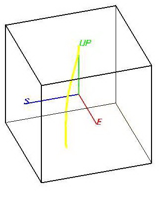 TVD
TVD| C- ADDITIONAL POST PROCESSING SOFTWARE MODULES
CORAL (COmplex Reservoir Analysis Lithology) This model provides an accurate, detailed description of reservoirs with mixed lithology. Its primary use is in the evaluation of formations, which contain shale, sand, limestone, dolomite, anhydrite, and gypsum. Minimum log data consists of a Gamma Ray or Spontaneous Potential, Induction or Laterolog resistivity, and Neutron and Density logs. Improved results are obtained if photoelectric (Pe), shallow resistivity, Sonic, Dielectric, and Spectral Gamma Ray data are used. SASHA (SAnd SHale Analysis) This model is designed to evaluate shaly sand reservoirs. The program computes the volume of shale, type of clay distribution, porosity, density of hydrocarbons, and water saturation. SASHA analysis is based on the Density-Neutron cross plot. Limited computations can also be accomplished when only one porosity device, or the combination Density-Sonic is available.THIN BED LARA (Laminated Reservoir Analysis) This makes use of dipmeter (or other high-vertical-resolution shale indicators) and a standard openhole log suite to analyze thinly laminated shaly sand reservoirs where clay content varies with depth. LARA’s algorithms determine shale volume, clay distribution, porosity, water saturation, and hydrocarbon density of thin-bedded formations. ULTRA (Universal Logging Tool Response Analysis) This is a weighted-least-squares error minimization technique which provides the analyst extensive flexibility to choose parameters, log measurements, and interpretive models. The effects of trace minerals, such as pyrite or ankerite, can be accurately evaluated with the ULTRA program. The analyst can also incorporate core results and other petrophysical data into ULTRA analysis to enhance the interpretation. |
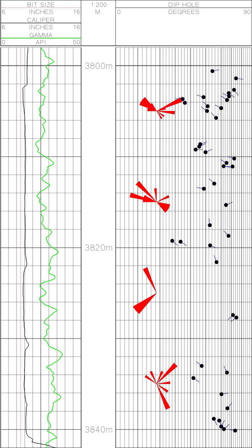 |
DIP ANALYSIS SHIVA A planar global mapping computational module for four or six arm dipmeters. SHIVA analysis relies on a weighted-least-squares optimization approach to make optimum use of redundant data. OMNI A global mapping computational module for curved surfaces for six arm dipmeters. OMNI is a variation of SHIVA analysis that evaluates non-planar bedding. If dips are planar. OMNI will produce the same dip angle and azimuth as SHIVA analysis. ORATOR Oriented resistivity processing of dipmeter data for fracture detection. ORATOR results also indicate the orientation of fracture anomalies. The ORATOR plot is made by comparing each diameter pad’s measurement with that of the adjacent pads.
|
|
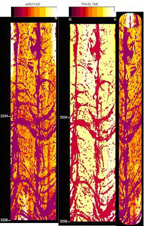
IMAGING - Pseudo 3D or Advanced 3D
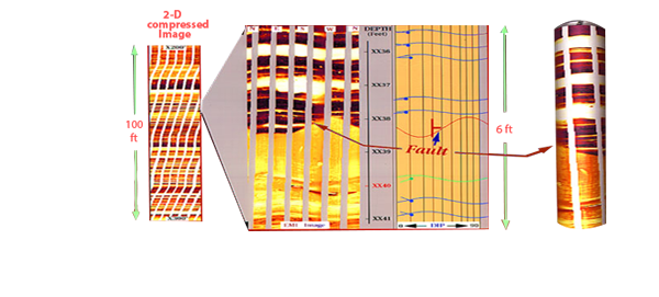
CAST Image enhancement of CAST data can be done to improve geologic interpretation, fracture analysis, and bed definition. This model allows histogram equalization of CAST data. CAST images can be plotted as 360 o two-dimensional or three-dimensional cylindrical images that can be rotated. Interactive dip and fracture plot can be obtained by matching a sinusoidal to the image features.
EMI Image enhancement of EMI data can be done to improve geologic interpretation, fracture analysis, and bed definition. This model allows histogram equalization of EMI data. EMI images can be plotted as two-dimensional or three-dimensional cylindrical images that can be rotated. Interactive dip and fracture plot can be obtained by matching a sinusoidal to the image features |
 |
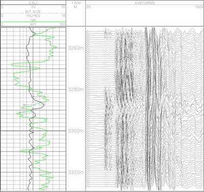 |
FULLWAVE ACOUSTIC allows processing of the acoustic waveform to compressional, shear and stoneley components by semblance correlation |
|
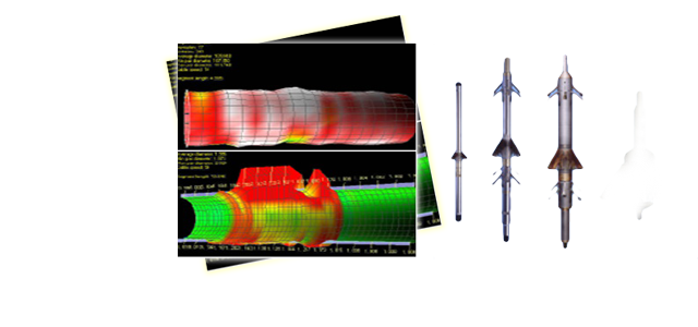
Mechanical Properties allows for rock elastic properties from Acoustic Dt compressional and shear combined with density measurements via ROCKXPERT. TRANSIENT PRESSURE (Pressure Transient Analysis) PTA evaluates the raw pressure-versus-time data recorded by formation testers. PTA output includes a modified pressure-versus-time plot, formation permeability and initial formation pressure. Both radial and spherical flow models are available and the results can be plotted as Horner or derivative plots.TRACERSCAN Seven models are used to evaluate the vertical and radial locations of radioactive tracer isotopes used to tag fracture, gravel pack, or cementing operations. The program uses CSNG spectra in a weighted least squares fitting technique to determine distributions for single or multiple tracers. |
Nhóm Marketing
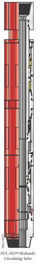
FUL-FLO® Hydraulic Circulating Valve
|
FUL-FLO® Hydraulic Circulating Valve The FUL-FLO® hydraulic circulating valve serves as a bypass around the packer or as a circulating valve to circulate a well after testing.When run below a closed valve, the tool serves as a bypas s around the packer and helps relieve pressure buildup below the closed valve when it is stung into a production packer.When run above a closed valve, the tool can be used as a circulating valve when the workstring is picked up. Features and Benefits • Permits passage of wireline tools through its full-opening bore • Requires no pipe rotation to operate Operation Bypass ports close when weight is set down and reopen when weight is lifted.A hydraulic metering system provides a 2 to 3-minute delay in closing after weight is applied. This delay allows either the RTTS packer to be set or the test string to be stung into a permanent packer before the bypass ports close. The ports reopen without a time delay.During stimulation work, the latching piston adds a downward force on the circulating sleeve to help keep the valve closed.Operation of the valve is the same whether it is used as a circulating valve or as a bypass. No torque is required. Weight is applied to close the tool, and the workstring is picked up to reopen it.
FUL-FLO Hydraulic Circulating Valve
Meets NACE-0175 > 175°F (79°C) standards for H2S service *Service temperature up to 450°F (dressed with 600 series o-rings and PEEK™ back-up seals) **The values of tensile, burst, and collapse strength are calculated with new tool conditions, Lame’s formula for burst and collapse strength, and stress area calculations for tensile strength. ***Pressure rating is defined as differential pressure at the tool. (Differential pressure is the difference in pressure between the casing annulus tool ID.) These ratings are guidelines only. For more information, contact your local Halliburton representative. PEEK is a trademark of ICI Americas, Inc. Poly-Ether-Ether-Ketone. |
Nhóm Marketing
Data Processing and Interpretation
Processing & Interpretation services
Processing and interpretation for openhole log data
- Processing and interpretation for sedimentary formation
- Processing and interpretation for basement rock
- Processing and interpretation for EMI,CAST-V, FULLWAVE/WAVESONIC data
Processing and interpretation for casedhole log data
- Processing and interpretation for PLT data
- Cement bond evaluation
- Casing and tubing inspection
- Processing and interpretation for well testing data
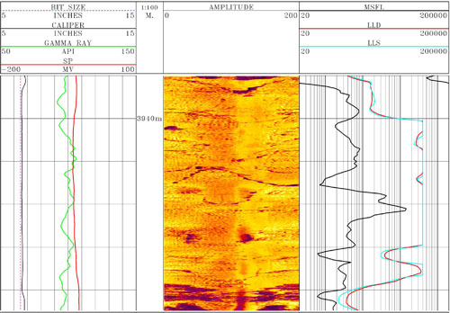
MicroSpherically Focused Log Resistivity
|
|
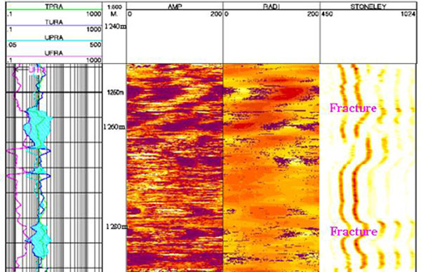
Opened fracture in White Tiger basement was detected by MSFL, DLL & CAST-V combination |
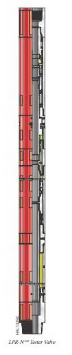
LPR-N™ Tester Valve
|
LPR-N™ Tester Valve
The LPR-N™ tester valve is a full-opening, annulus pressure-operated valve. It measures multiple closed-in pressures in cased holes where pipe manipulation is restricted and a full-opening string is required. The nitrogen chamber is charged at the surface to a selected pressure determined by surface temperature, bottomhole temperature, and bottomhole pressure. If the intended test requires a permanent packer that uses a stinger mandrel or seal nipple, a variety of Halliburton bypass tools are available, depending on field application, to help ensure that the formations and downhole equipment are protected from excessive pressure buildup. Features and Benefits
• The ball valve operates independently of internal pressure changes, such as with acidizing or fracturing operations. • Advanced materials and processes provide a unique metal-to-metal seat for exceptional gas-holding capabilities. • The LPR-N tester valve has been through an extensive five-day qualification testing at 400°F and 15,000 psi burst and collapse pressures. • An open-in feature allows the operator to run the LPR-N tester in the hole with the ball valve opened or closed. • Fluids can be spotted or circulated through the LPR-N tester with the packer unseated.A double nitrogen chamber can be added to the LPR-N tester for use in deep, hot, high-pressure wells to reduce the operating pressure. Operation
The LPR-N tester valve is composed of a ball valve section, a power section, and a metering section. The ball valve section provides multiple downhole closures. It is turned by operating arms. The power section has a floating piston that is exposed to the hydrostatic pressure on one side and pressurized nitrogen on the other side. With the packer set, pump pressure applied to the annulus moves the piston downward, activates the operating arms, and opens the ball valve. When the annulus pressure is released, pressurized nitrogen returns the piston upward, closing the ball.After the surface equipment is properly installed, the packer is set, and the rams are closed, pressure is applied to the annulus, using rig pumps to operate the LPR-N tester. To begin testing, quickly apply pump pressure to the annulus to a predetermined pressure, and hold for 10 minutes to pressurize the nitrogen chamber. After pressure has been metered through the metering cartridge, pressure in the nitrogen chamber will be slightly less than combined hydrostatic and pump pressure in the annulus. This helps ensure that the ball valve stays open during testing or treating operations. The closing force may be increased on wells with an extremely high flow rate and wells producing a large amount of sand. Before the tool is closed, the annulus pressure is increased to a predetermined safe pressure below the operating pressure of the circulating valve and held for 10 minutes. This procedure creates additional closing force when the annulus pressure is released. Releasing the annulus pressure as quickly as possible closes the ball valve. A minimum of 10 minutes is needed to allow excess closing pressure in the nitrogen chamber to equalize before annulus pressure is reapplied. It is best to use the highest safe operating pressure to obtain maximum closing force. LPR-NTM Tester Valve
Meets NACE-0175 > 175°F (79°C) standards for H2S service *Service temperature up to 450°F (dressed with 600 series o-rings and PEEK™ back-up seals) **The values of tensile, burst, and collapse strength are calculated with new tool conditions, Lame’s formula for burst and collapse strength, and stress area calculations for tensile strength. ***Pressure rating is defined as differential pressure at the tool. (Differential pressure is the difference in pressure between the casing annulus tool ID.) These ratings are guidelines only. For more information, contact your local Halliburton representative. PEEK is a trademark of ICI Americas, Inc. Poly-Ether-Ether-Ketone. |
Nhóm Marketing
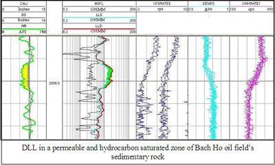
Dual Latelog
| In order to use the latest techniques in wireline logging and for more effective analysis in sedimentary and basement rock, from 1997 Vietsovpetro Logging & Testing division has been using Halliburton’s Dual Laterolog Tools (DLL-T).
Dual Laterolog service provides reliable means of measuring formation resistivity in conductive borehole fluids under harsh downhole conditions. Accurate resistivity measurements are critical for
|
|

|
 |
|
Benefits and Features
The tool is calibrated with an advanced calibration system.
The tool employs dual electrode arrays and an automatic current-focusing technique.
Rugged construction and quality electronics help ensure that the tool functions properly at elevated temperatures and pressures. |
 |
The DLL tool is combinable with a complete family of tools that operates under Halliburton’s Digital Interactive Telemetry System. Nhóm Marketing |
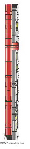
OMNI™ Circulating Valve
|
OMNI™ Circulating Valve The OMNI™ circulating valve is an annulus pressure-operated, recloseable circulating valve. Throughout the operation, the tool is repeatedly cycled up to a predetermined annulus pressure and then released.
The OMNI valve consists of a nitrogen section, an oil system, a circulating valve, and a ball valve. The nitrogen section contains the nitrogen gas that counterbalances the hydrostatic and annulus pressures. The amount of nitrogen in the tool depends on well hydrostatic (mud weight and depth) and downhole temperature. This information must be known to properly prepare the tool for running in. Note: With certain completion fluids, the mud weight at the surface can be significantly different from the actual mud weight downhole.
The operating and control mechanisms are contained in a closed oil system activated by annulus pressure acting on the nitrogen chamber, allowing an unlimited number of pressure cycles.The circulating valve and the ball valve work together to keep circulating pressure off the formation. The ball valve will close before the circulating valve opens. The ball valve closes off the workstring.
Features and Benefits
• Permits well testing, pressure testing, and fluid circulation • Allows unlimited number of pressure cycles
|
| Operation
The well can be flow tested when the valve is in the well test position. When in this position, the circulating ports are closed and the ball valve is opened. During a downhole closure drillstem test, the OMNI valve is in the well test position during flow and shut-in periods. The workstring can be pressure-tested in the blank position because the ball valve closes before the circulating valve opens. Fluid can be pumped in either direction through the tool in the circulating position. In this position, the circulating ports are open and the ball valve is closed.Note: Before the tool is run, the hydrostatic pressure at the specified tool depth must be known. This information is required to obtain the proper nitrogen charging pressure. OMNITM Circulating Valve
Meets NACE-0175 175°F (79°C) standards for H2S service *Service temperature up to 450°F (dressed with 600 series o-rings and PEEK™ back-up seals) **The values of tensile, burst, and collapse strength are calculated with new tool conditions, Lame’s formula for burst and collapse strength, and stress area calculations for tensile strength. ***Pressure rating is defined as differential pressure at the tool. (Differential pressure is the difference in pressure between the casing annulus tool ID.) These ratings are guidelines only. For more information, contact your local Halliburton representative. PEEK is a trademark of ICI Americas, Inc. Poly-Ether-Ether-Ketone. |
Nhóm Marketing
Open hole logging
1. INTRODUCTIONS 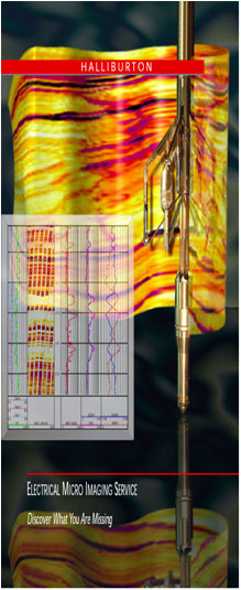
Services
- Electrical logs: DLL, MSFL, HRI, Dipmeter, EMI.
- Radioactive logs: LDL, CNL, SGR, GR.
- Acoustic logs: BHC, FWSL, Crossed dipole wavesonic log, Bore hole televiewer, Vertical seismic profile.
- Others: Caliper, Deviation survey…
- Toolpusher
- VSP (Vertical Seismic Profile)
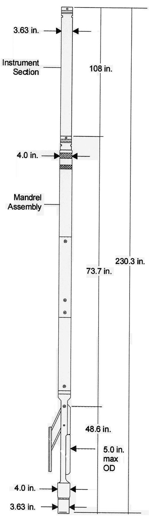
Instream Gauge Carrier
Instream Gauge Carrier 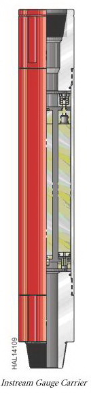
Instream gauge carriers carry as many as four pressure or temperature gauges in the flow stream to monitor downhole conditions while maintaining a full opening through the tools. The carriers are designed to carry 1.25-in. (31.75-mm) diameter electronic or mechanical gauges. Recorders are suspended on the inside of the running case, which has cushioning devices to protect the gauges from shock. Features and Benefits• Permits unrestricted flow through the tools • Allows wireline operations to be run • Facilitates a faster response to temperature changes
Instream Gauge Carrier
Meets NACE-0175 175°F (79°C) standards for H2S service *Service temperature up to 450°F (dressed with 600 series o-rings and PEEK™ back-up seals) **The values of tensile, burst, and collapse strength are calculated with new tool conditions, Lame’s formula for burst and collapse strength, and stress area calculations for tensile strength. ***Pressure rating is defined as differential pressure at the tool. (Differential pressure is the difference in pressure between the casing annulus tool ID.) These ratings are guidelines only. For more information, contact your local Halliburton representative. PEEK is a trademark of ICI Americas, Inc. Poly-Ether-Ether-Ketone. |
Nhóm Marketing