
L&TD
LOGGING & TESTING DIVISION
Sản phẩm dịch vụ
Surface Logging System & Excell 2000 Application
 Time spent at the wellsite is a valuable commodity. How this time is utilized is even more important. If time is not taken to properly analyse and study all available data, decisions that can adversely affect future production of your well or field might be made. Conversely, if too much time is spent at the wellsite, delays in the well program can occur. It all relates back to one thing.
Drain Valve
|
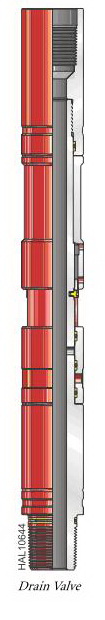
Drain Valve
The drain valve consists of a ported body, sliding sleeve, and rotating nut, which contr ols the position of the sliding sleeve. The sleeve either covers or exposes the ports in the body of the valve. The drain valve is suitable for sour service at all temperatures. A drain collar and associated components are required when relieving pressure. Features and Benefits
• Allows pressure trapped between two closed valves to be relieved in a controlled manner • Used to recover large volume fluid samples Operation
The drain valve is installed between any two valves that may come out of the hole with pressure or fluid trapped between them. Pressure is relieved by installing the drain collar and drain nipples on the drain valve. Valves, lines, or sample bottles may be attached to the drain nipples depending on the desired disposition of the fluid in the string. After the drain collar assembly is attached, the ports in the tool are exposed by using a chain wrench or pipe wrench to rotate the drain nut, which moves the sliding sleeve.When the ports in the sleeve are aligned with the ports in the body of the tool, the fluid may be drained.It is also possible to trap a large volume fluid sample between two valves if a sample chamber of some kind (tubing, drill collar, etc.) is placed between the valves. In most cases, the drain valve would be run at the bottom of the sample chamber to facilitate transfer. This will not be a PVT sample.
Drain Valve
Meets NACE-0175 175°F (79°C) standards for H2S service *Service temperature up to 450°F (dressed with 600 series o-rings and PEEK™ back-up seals) **The values of tensile, burst, and collapse strength are calculated with new tool conditions, Lame’s formula for burst and collapse strength, and stress area calculations for tensile strength. ***Pressure rating is defined as differential pressure at the tool. (Differential pressure is the difference in pressure between the casing annulus tool ID.) These ratings are guidelines only. For more information, contact your local Halliburton representative. PEEK is trademark of ICI Americas, Inc. Poly-Ether-Ether-Ketone. |
Nhóm Marketing
Rupture Disk Safety Circulating Valve
|
Rupture Disk Safety Circulating Valve The rupture disk (RD) safety circulating valve functions as both a safety valve and circulating valve. The tool functions as a safety valve when the annulus pressure reaches a predetermined value. At that pressure, the valve isolates the workstring below the tool and establishes communication between the annulus and the workstring above the tool. This tool converts into a circulating valve when the ball valve section is removed. Features and Benefits The tool is composed of three major sections: • The power section consists of a power mandrel case and rupture disk that is available for a wide range of pressure applications. The rupture disk bursts at a predetermined pressure, allowing annulus pressure to be applied to a differential area on the power mandrel. The power mandrel moves down, first pushing the ball valve closed, and then opening a set of circulating ports. • The circulating section consists of a set of ports that are initially sealed by the power mandrel. When the rupture disk bursts, the power mandrel moves down, exposing the ports that allow communication between the annulus and workstring. • The safety valve consists of a ball valve, operating pins, and collet fingers. As the power mandrel moves down, the operating arms close the ball valve. The collet fingers expand, allowing the power mandrel to continue traveling down to open the circulating ports.
Operation
Before the RD safety circulating valve is used, the operating pressure is calculated for selecting the proper rupture disk pressure rating. Required information includes mud weight, testing depth, bottomhole temperature, and maximum annulus pressure. When the rupture disk safety circulating valve is run with an annulus pressure-operated valve, the safety valve operating pressure should be kept 1,000 psi above the operating pressure of the tester valve. Ruptute Disk (RD) Safety Curulating Valve
|

Nhóm Marketing
Slip Joints
|
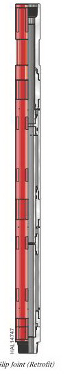
IV. DOWNHOLE TESTING EQUIPMENT Slip Joints A slip joint compensates for the movement associated with ocean heave or temperature change without allowing the movement to disturb the placement of downhole tools. A slip joint operates by balancing its volume. As the slip joint stretches and increases its internal volume, a differential piston within the slip joint allows the same volume of fluid into the pipe. The net result is no change in internal volume. Each slip joint has 5 ft of travel but can be combined with other slip joints to provide additional travel. Slip joints are designed to transmit the torque or rotation required to operate tools such as packers or safety joints. When multiple slip joints are run, they are normally connected together rather than located throughout the pipe string. The number of slip joints required depends on ocean heave and the amount of expected contraction and expansion. Features and Benefits
• Provides a variable-length joint to allow expansion and contraction of pipe during testing or stimulation • Helps space out the workstring when the subsea tree is landed • Keeps vertical movement of drilling vessel from disturbing tool placement • Provides free travel in workstring to reciprocate tools Operation
The weight of the workstring (excluding tools, anchor, and traveling blocks) is used to determine the location of the slip joint. The slip joint(s) are placed above the necessary packer setting weight.When multiple slip joints are used, the top joint makes its complete travel, then the next joint down makes its travel, and so on. The weight indicator may show a slight bump as each slip joint reaches the end of its travel. |
 |
Nhóm Marketing
Subsurface Testing Equipment
|
III. SUBSURFACE TESTING EQUIPMENT
Ocean Floor Package
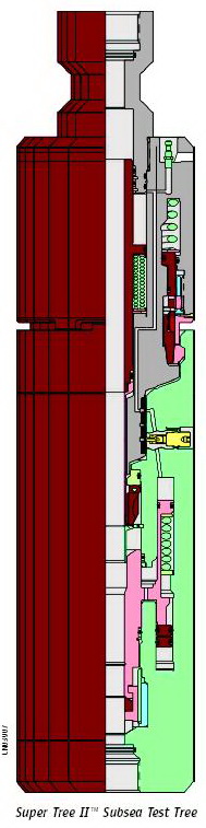
The SSTT consists of two full-pening/normally closed, fail-safe safety valves and a latchrelease connection. The valve section contains two tubing closures. Each closure operates independently of one another, and each relies on a single hydraulic source to hold it open. A normally closed . apper valve and a ball valve are closed by a nitrogen chargeassisted spring force. The nitrogen charge forces the ball to sever wireline or 1.25-in. OD, .125-in. wall thickness coiled tubing. A short time delay between the nitrogen charge and ball/. Apper closure allows severed wireline or coiled tubing to be pulled clear of the . apper before closure. The latch section consists of a latch to the valve section, a flapper-operating piston, and molded seals. The latch section is designed to quickly release the handling string from the SSTT in case of an emergency.
Features and Benefits • Normally closed, fail-safe valve • Releases quickly from the handling string in case of emergency • Functions as a safety device • Maintains pump-through capabilities at all times • Nitrogen dome charge chamber provides increased closing force and lessens the time required for closing • Can unlatch under tension • Redundant seal design • Chemical injection at the valve body, further downhole to an injection sub, or to actuate a sub-surface safety valve • Capable of cutting 2-in. OD, .125 wall-thickness coiled tubing |
 |
|
|
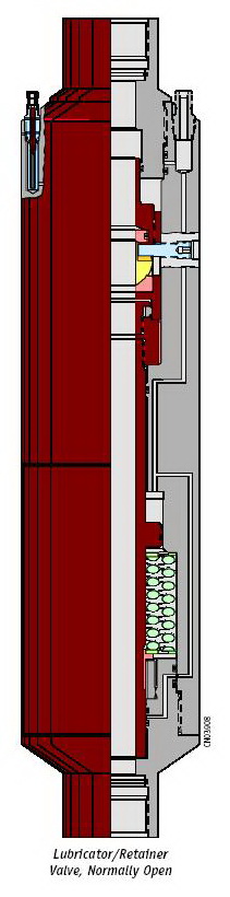
Lubricator/Retainer Valve The Lubricator/Retainer Valve is a tubing-retrievable valve. The placement of the valve in the subsea welltesting string determines whether the tool functions as a Lubricator or Retainer Valve. The valve can function as either a normally open or normally closed/fail-safe ball valve. It is operated from the surface by control lines. When used as a Lubricator Valve, it is installed at a predetermined depth beneath the drill floor. The valve and the workstring above it serve as a lubricator for wireline tools. This installation replaces the need for surfacemounted lubricators. In the lubricator position, the valve can also be used to prove the integrity of the lubricator section by pressure testing from above. When used as Retainer Valve, it is installed directly above the Subsea Test Tree (SSTT) near the ocean floor. Its primary function is to capture well. Fluids that would be trapped in the handling string during an unlatch of the SSTT. Additionally, the valve can be used to prove the integrity of the handling string before the well is brought on line.
Features and Benefits • Retainer dual mode cabilities: normally open or normally closed/fail-safe • Can be used as a Lubricator Valve for wireline tools • Can be used as a Retainer Valve to capture well . uids from the handling string • Normally open holds pressure from below and selectively seals from above |
 |
|
Lubricator/Retainer Valve |
| P/N | 617.20100 |
617.20300 |
| OD In (cm) | 10.75 (21.31) | 10.75 (21.31) |
| ID in. (cm) | 3.00 (7.62) | 2.7 5 (6.99) |
| End Connections | 4 1/2 - 4 ACME | 5-4 ACME |
|
Length in. (cm) |
71. 44 (181.46) |
74. 64(198.59) |
| Tensile Rating* lb (kg) |
400,000 (181, 000)) |
400,000 (181,000) |
| Working Pressure** psi (kPa) | 10,000 (69,000) | 15,0 00 (103,500) |
| Service | H2SH | H2S |
| 0 to 350 (-18 to 177) | 0 to 350 (-18 to 177) |
Nhóm Marketing
Surface Testing Equipment
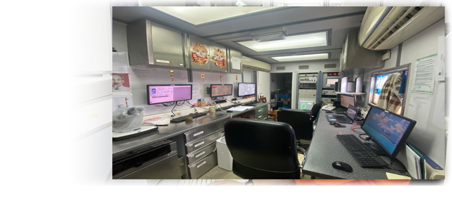
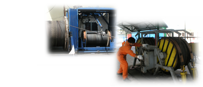
VIETSOVPETRO well testing service was formed since 1987 and has been successfully tested hundreds of wells on White Tiger, Big Bear field , Soi and Hoang Long objects on Vietnam offshore, etc. VIETSOVPETRO well testing team has five highly experienced Engineers, two skilled technicians. Most of them have more than 10 years working experience. Beside of testing on Jack up, Semi Sub sea, Engineers of team also performed testing data analysis, Reservoir parameters are interpreted by Saphir software of KAPPA .co. |
Well Testing
Equipment
- 2 surface fully work-out testing systems supplied by Flopetrol Jonston Co. (Include: Well head, flexible hose, choke manifold, three phases separator, surge tank, transfer pump, pipe work, compressor, burner boom, hydrometer, etc.)
- 1 SubSea equipment supplied by PowerWell Co.
- 2 DownHole equipment (DST) supplied by Halliburton co. ( 2006 year)