L&TD
LOGGING & TESTING DIVISION
Open hole logging
1. INTRODUCTIONS 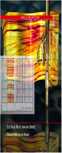
Services
- Electrical logs: DLL, MSFL, HRI, Dipmeter, EMI.
- Radioactive logs: LDL, CNL, SGR, GR.
- Acoustic logs: BHC, FWSL, Crossed dipole wavesonic log, Bore hole televiewer, Vertical seismic profile.
- Others: Caliper, Deviation survey…
- Toolpusher
- VSP (Vertical Seismic Profile)
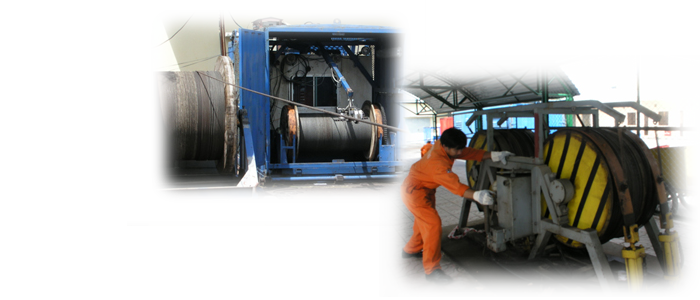
Equipment
- 03 Halliburton’s Logging Units
- 04 Russian’s new-tech Logging Units
- 02 Huanding’s Logging Units
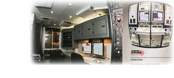
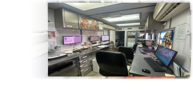
Surface Logging System & Excell 2000 Application
Excell 2000 Application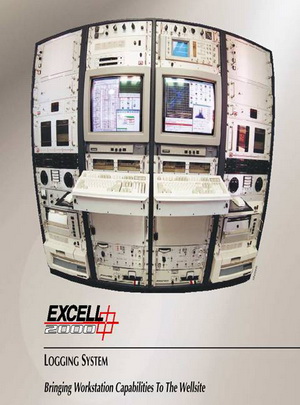
- Complete openhole logging services
- Complete casedhole logging services
- Production logging
- Real-time display of borehole images via the EMI ™ and CAST ™ services
- Completion services including setting packers and bridge plugs, perforating, pipe recovery, and chemical cutter
- Verifying and evaluating stimulation, cementing, and gravel pack operations
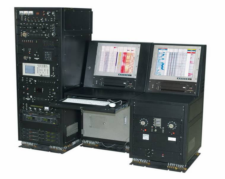
LOGIQ-B SURFACE LOGGING SYSTEM :
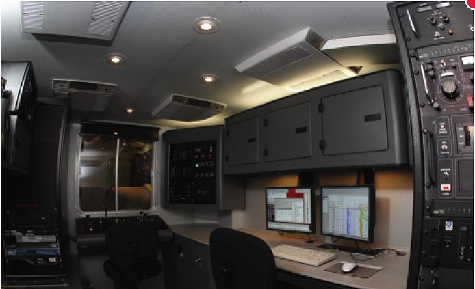
The LOGIQ-B Logging System is the next generation of Data Acquisition Systems for Halliburton Wireline Logging Services. For Open Hole Services, the logging software runs under the new platform on a Rack Mount based Windows 2000 environment to provide remote controlled capabilities, real-time petrophysical data acquisition services.
For Cased Hole Services, the Cased Hole Software running under Windows 2000 provides real time monocable data acquisition services. The LOGIQ Logging System has three main subsystems:
•The Tool Power Subsystem
•The Tool Interface Subsystem
•The Processing Subsystem
Tools Specifications
- Max Temp: 3500F. Max press: 20 000 psi
- Max hole: 24”. Min hole: 4.5”
- High Sensitivity & Accuracy
- Logging Speed: 30 – 100 ft/min
- LDL: Full Spectral Analysis
- Dipole Sonic: 96 Full Wave Forms
- EMI: 6 independent arms, 150 sensors
- CAST-V: 200 shots/scan.
DUAL LATEROLOG
| Max Temp |
| Max press |
|
| Max hole | |
| Min hole |
| Vertical Resolution | ||
| Depth of Investigation (50%) | ||
| Sensitivity | ||
| Accuracy, High | ||
| Accuracy, Low | ||
| Primary Curves |
| Secondary Curve |
Dual Laterolog service provides reliable means of measuring formation resistivity in conductive borehole fluids under harsh downhole conditions.
Applications
- Accurately computing hydrocarbon saturation
- Delineating thin beds
- Indicating permeable zones and estimating invasion diameter (when used with an appropriate Rxo measurement)
- Identifying formation fluid contacts within the reservoir
- Acquiring optimum formation resistivity measurements when the contrast between formation resistivity and borehole-fluid resistivity is very high
- Indicating fracture zones in both sedimentary and basement rock
MICROSFERICALLY FOCUSED LOG
Tool specification
| Principle | |
| Max Temp | |
| Max Press | |
| Max hole | |
| Min hole | |
| Range |
| Vertical Resolution | ||
| Depth of Investigation (50%) |
| Sensitivity | |
| Accuracy | |
| Primary Curves | |
| Secondary Curve |
Applications
- Resistivity of flushed zone
- Locate porous and permeable zones
- Delineate thin beds
- Estimate porosity
- Movable hydrocarbon indication
- Caliper
COMPENSATED SPECTRAL NATURAL GAMMA RAY
Tool specifications
| Principle | |
| Max Temp | |
| Max Press | |
| Max hole | |
| Min hole | |
| Vertical Resolution (90%) | Enhanced 18 in. (458.64 mm) |
| Depth of Investigation(50%) | |
| Precision (1 SD) | |
| Accuracy: | |
| Primary Curves | |
| Secondary Curves |
Applications
- Detect producible zones
- Increase reservoir understanding
- Determine clay types, volumes, and action exchange capacity
- Locate radioactive tracers
- Identify lithology or determine average casing thickness
- Basement’s fracture zones quick indicator
SPECTRAL DENSITY LOG
Tool specifications
| Max Temp | |
| Max Press | |
| Max hole | |
| Min hole |
| Vertical Resolution (90%) | |||
| Depth of Investigation | |||
| Precision (1 SD) |
| Primary Curve | |
| Secondary Curve |
Applications
- Accurate determination of formation bulk density
- Reliable identification of formation lithology, regardless of formation fluid type
- Precise delineation of thinly bedded formations (the unfiltered Pe curve is used)
- Excellent indication of gas when used in combination with a neutron log
- Excellent effect of basement dyke identification when used in combination with a neutron log
DUAL SPECTRAL NEUTRON
Tool specification
| Max Temp | |
| Max Press | |
| Max hole | |
| Min hole |
| Vertical Resolution (90%) |
| Depth of Investigation(50%) |
| Precision (1 SD) |
| Accuracy, Low |
| Primary Curves |
| Secondary Curve | |
| Source |
Applications
- Superior accuracy
- Repeatable results
- Improved thin bed evaluation
- Increased reservoir understanding
- Faster log runs
- Gas detection
- Dykes detection
BOREHOLE COMPENSATED SONIC
Tool specification
| Principle |
| Max Temp | ||
| Max Press | ||
| Max hole | ||
| Min hole | ||
| Range | ||
| Vertical Resolution (90%) | ||
| Depth of Investigation (50%) | ||
| Sensitivity | ||
| Accuracy |
| Primary Curves |
| Secondary Curves |
Applications
- Porosity analysis
- Lithology identification
- Abnormal pressure identification
- Velocity data for seismic studies
- Fracture identification
FULLWAVE SONIC
Tool specifications
| Approximate Overall Length ·Standard configuration ·Extra-Long configuration |
728 in. |
18.49 m |
| Temperature Rating | ||
| Pressure Rating | ||
| Recommended Hole Sizes ·Minimum Borehole Diameter ·Maximum Borehole Diameter |
20 in. |
508 mm |
| Transmitter ·Type ·Resonant Frequency |
15 kHz |
| Receivers ·Type ·Frequency Response |
Flat from 700 Hz to 30 kHz |
| Transmitter-To-Receiver Offsets Standard Configuration Extra-Long Configuration Short Configuration |
ft 17.5, 18.5, 19.5 and 20.5 ft 3 and 5 ft |
and 3.96 m 5.33, 5.64, 5.94 and 6.25 m 0.91 and 1.52m |
Applications
- Improved porosity estimates using both Tc, and Ts.
- Lithology identification by means of velocity ratio, Ts /Tc.
- Location of gas zones, even in poor hole conditions and cased holes
- Indication of permeability variations with depth from Stoneley wave attenuation
- Detection of naturally fractured zones
- Determination of rock elastic constants
- Estimation of formation strength and least horizontal stress
- Prediction of vertical extent of hydraulic fractures
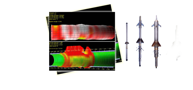
WAVE SONIC
Tool specifications
| Principle |
| Max Temp | ||
| Max Press | ||
| Max hole | ||
| Min hole |
| Range |
| Vertical Resolution (90%) | ||
| Depth of Investigation (50%) |
| Sensitivity | |
| Resolution | |
| Primary Curves | |
| Secondary Curves | Anisotropy, Poisson’s ratio, Stoneley slowness |
This is an example of a semblance diagnostic plot of the waveform data from the eight waveforms. In the circle is a section of a WaveSonic log showing Monopole P wave slowness and semblance quality monopole refracted Shear wave
The Product of Superior Technology
WaveSonic tool service provides simultaneous monopole and crossed dipole sonic information. P‑wave and S‑wave slowness can be obtained in formation conditions ranging from poorly consolidated high porosity gas saturated sandstones to low porosity carbonates.
Other benefits include
- Low frequency monopole and dipole sources for deeper investigations of sonic slowness measurements beyond any near wellbore alteration effects Broadband eight‑level, quad receiver array for high quality waveform data
- State‑of‑the‑art tool design is an extension of the robust Sperry‑Sun LWD BATTM Sonic
- Combinable with all openhole tools, including MRIL and RDTTM
- On‑depth, low frequency bender bar source provides a clean source signal.
- No need for dispersion corrections for slowness determination.
- No depth shifting of waveform data for anisotropy analysis.
- Robust tool isolator design allows for drill pipe conveyed operations; WaveSonic tool not limited to bottom of tool string
SIX ARM DIPMETER
Tool specifications
| Principle |
| Max Temp | |
| Max Press | |
| Max hole | |
| Min hole |
| Vertical Resolution (90%) | |||||
| Depth of Investigation (50%) | |||||
| Accuracy |
| Primary Curves | |
| Secondary Curves |
Applications
- Determine magnitude and direction of formation dip
- Identify structural and stratigraphic events
- Identify fractures
- Provide drift survey
- Determine true vertical depth
- Determine exact location of bottom hole
- Provide borehole profile and cement volume calculations
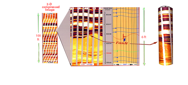
ELECTRICAL MICRO IMAGING
Tool specification
| Maximum Temperature | ||
| Maximum Pressure |
| Measurement Range |
| Resistivity Imager | ||
| Dipmeter Processing | ||
| Resolution | ||
| Maximum Hole Size | ||
| Minimum Hole Size |
| Number of Buttons | |
| Number of Pads |
IMAGING – THE KEY TO BETTER ANALISYS 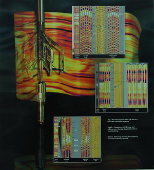
Real-time images are produced at the wellsite. Detailed post-acquisition analysis of the image data is made with high-performance InterView ™ analysis software. Image analysis and enhancement techniques are available for precise identification of formation reservoir characteristics, including the following:
• Detailed stratigraphic and sedimentological analysis. Identification and Characterization of Sedimentary Features
• Thin bed delineation
• Fracture analysis
• Fault Identification and Orientation
• Identification and Orientation of Secondary Porosity
HIGH RESOLUTION INDUCTION
HRI Tool specification
| Medium |
| Max Temp | |
| Max Press | |
| Max hole | |
| Min hole | |
| Range |
| Vertical Resolution (90%) | (30.5 or 61 cm) |
(30.5 or 61 cm) |
(<43cm) |
| Depth of Investigation (50%) | (231 cm) |
(99.06 cm) |
(<43cm) |
| Sensitivi | |||
| Accuracy | or ± 1 ohmm |
or ± 1 ohmm |
| Primary Curves | |
| Secondary Curves |
CAST-V
Primary applications include
- Open Hole Borehole Imaging
- Fracture Detection
- Casing Inspection (Both Thickness And Diameter)
- Ultrasonic Cement Evaluation/ Imaging
The energy levels of reflected ultrasonic wave have been used
- To locate the fracture zones
- To differentiate between open fractures and filled fractures
- To determine the geometric characteristics of fractures: dip, azimuth dip, and aperture
- In fact, surveys in basement of Cue long basin indicated that CAST-V is the most effective tool for studying basement fractures.
HUANDING SYSTEM
HH-2530 HARDWARE
- 530 main computer and 530 auxiliary computer constitute dual-computer system to complete 530, 520, 521 and WTC production loggings and perforating and sidewall coring.
- The software is of OPERATIONAL SYSTEM Windows-2000 to establish an open platform.
- If the 530 main computer has trouble, the auxiliary computer can enter the system quickly through Ether net port of Network exchanger to replace the 530 main computer continue the logging task.
530-Series: High Reliability Logging Tools
530-SERIES TOOL STRING
TTR: Temperature/Tension/Rm Tool
TGR: Telemetry & Gamma Ray Sub
HAS: Hydraulic Pad-mounted Device
SGS: Spectro Gamma Ray Sonde
CNS: Compensated Neutron Sonde
NEC: Common Electronic Circuit Section 1
LDS-MFS: LDT and MSFL Combined Sonde
BDS: Borehole Deviation Sonde
REC: Common Electronic Circuit Section 2
DLS: Dual Latero-logging Sonde
HRAS: HR Sonic Sonde
DIS: Dual Induction Sonde
FJS: Flexible Joint Sub
D4C: 4-independent Arm Caliper
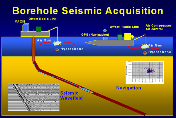
VERTICAL SEISMIC PROFILE
Tool Specifications
-
Up to 42 satellites
-
Real time data transmission
-
24bit Delta-Sigma convertors
-
180oC temperature rating Unique Active Cooling System for continuous operation at 180oC
-
20000psi pressure rating
-
Up to 95m between satellites
TOOLPUSHER
Applications
- Toolpusher is a tool transport system use to convey the logging tools to the bottom of the well.
- Able to log any angel well
- Same log quality as standard tools
- Tools always attached to drillpipe
- Mud circulation past the tools
- Able to log long intervals
- Accurate depth control
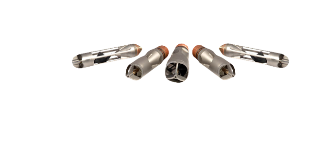
ROTARY SIDEWALL CORING TOOL (RSCT)
The RSCT™ tool diamond-drills cores perpendicular to the borehole wall with continuous monitoring of the coring process. After gamma ray depth positioning, a backup shoe is extended to decentralize and hold the tool securely against the formation. A diamond bit rotating at 2,000 rpm cuts a 0.9375-in OD, 1.75-in. long sample from the formation. Surface control of weight-on-bit optimizes drilling.
RSCT Tool Features
The RSCT tool contains the following features
• Allows 30 or more cores to be taken in one run
• Can be run on Toolpusher™ logging system or coiled tubing to acquire cores in deviated, extended reach, and horizontal wells
• A core length indicator takes the guesswork out of core recovery
• Stand-alone tools can be run on third-party logging units
RSCT Tool Benefits
• Formations. Originally designed to recover cores in hard rock formations inaccessible with percussion tools, the RSCT can be used with equal success in soft rock formations.
• Positive Depth Correlation. Gamma ray tool positioning provides accurate core point location.
• Drills Undistorted, Non-Micro Fractured Cores. Core samples are undistorted with consistent cylindrical geometry which allows a wide range of petrophysical testing and analysis.
• Useful in Formation Damage Assessment. Allows for evaluation of pre-existing formation damage.
Rotary Core Applications
Rotary core samples collected by the RSCT tool can be used to provide
• More accurate readings of porosity and permeability that reduce reservoir analysis variables.
• Information useful in fine-tuning MRIL® data.
• Reliable data for rock mechanical analysis necessary for hydraulic fracturing design, wellbore stability analysis, and sand potential prediction
ExperienceS
- White Tiger Project: Over 300 Wells
- Dragon Project: Over 50 Wells
- Hoang Long Project (PIDC) 1 Well
- PVEP’s Projects: 10 Wells
- VRJ’s Projects: 2 Wells
- JVPC Projects: 7 Wells
- KNOC Projects: 4 Wells
- 15 – 20 Well/Year.
Nhóm Marketing