
L&TD
LOGGING & TESTING DIVISION
Well testing
Advantages & Disadvantages
|
ADVANTAGES
DISADVANTAGES
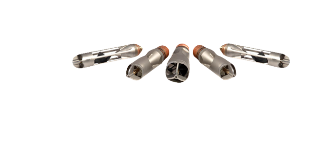
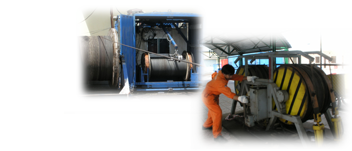
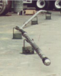
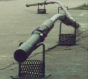
Rig up and logging takes longer than standard logging 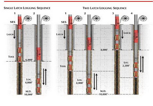 Picture of TPL drillpipe conveyed system |
Nhóm Marketing
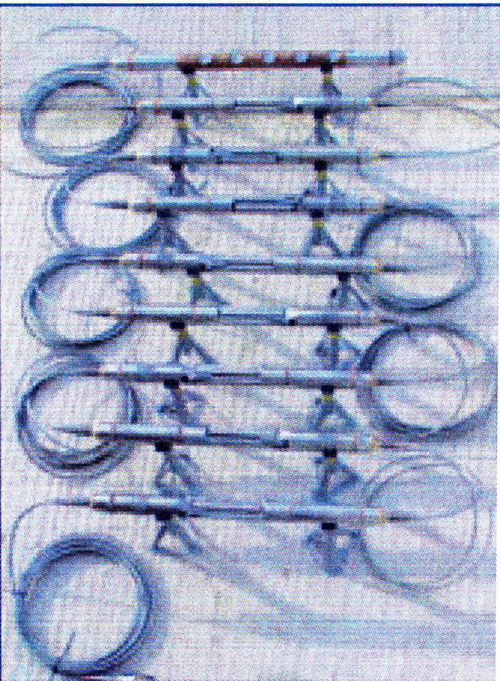
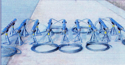
Toolpusher Assemblies
 |
Nhóm Marketing
Vsprowess Software
|
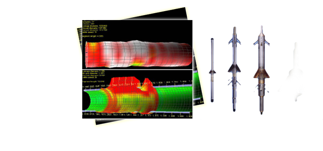
Main Features • Three component processing of any survey configuration • Image reconstruction of P and S wave modes, both CDP mapping and migration, using simple dip, anisotropic models. • Time slice display of 3D datasets • Proximity surveys including anisotropy and simple dip • Q estimation • Wavelet extraction/matching • AVO/ • Fracture monitoring display • Flexible display options • Input data formats include SEGY, • Velocity log calibration and synthetic seismogram • Import and display of LAS logs. 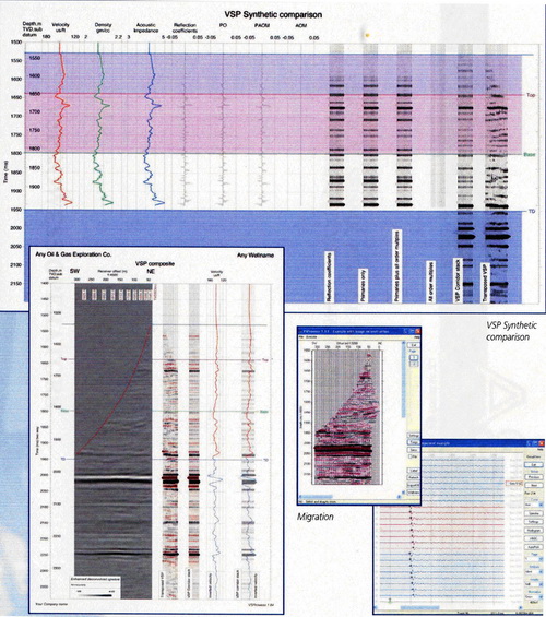 |
Nhóm Marketing
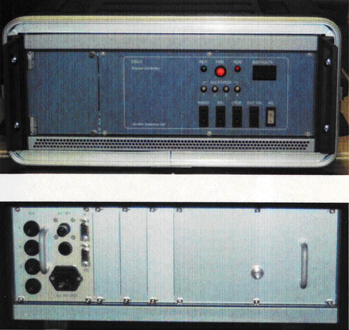
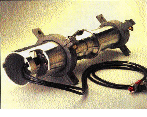
Airgun And RSS-2 VSP Source Controller
|
I/O Sleeve Guns
• Size: three sizes, with volumes of 10 in3,20 in3 or 40 in3. • Polarized timing coil • Measured standard deviation of 110µs with a 351µs dispersion • Tow clamps equipped with a top hat that minimizes electrical cable and air hose proplems during handing and RSS-2 VSP Source controller
• Automatic source array synchronisation • Window based software • Each RSS-2 controls up to 16 sources |
|
 |
• Timing accuracy 0.1ms • Source signature telemetry • Readout of reservoir and gun pressure • Accepts hydrophone, shuttle, T/B coil etc • Automatic source switching from software
|
Nhóm Marketing
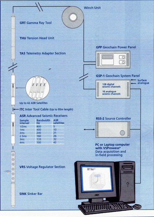
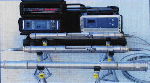
Downhole Tool GeochainTM 42 Level Digital VSP Array
|
Main Features: • Up to 42 satellites • Standard 7 conductor wireline. • Real time data transmission • 3 component gimballed • 24bit Delta-Sigma convertors • 180oC temperature rating • Unique Active Cooling System for continuous operation at 180oC • 20000psi pressure rating • Up to 95m between satellites |
8 satellites and VRS |
|
GeochainTM – an 8 level array with VRS
|
Nhóm Marketing
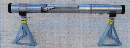
Downhole Tool ASR-1 Advanced Seismic Receiver
 The ARS-1 Specifications
General
The ASR geophones a compact three component electromechanical downhole geophone. It is disigned for use in wells up to 20000psi and 200oC and provides fast arm cycle time with an arm force to weight ratio of 5:1.
Locking Arms The standard arm will accommodate boreholes from 5” to 13”, the short arm will accommodate borehole from 3 ½” to 9” and an extended arm can be use to increase this range to 22”. The locking force is constant to within 20% throughout its operating range and will lock into 9 5/8” casing in fifteen seconds when fitted with the standard arm. Gimbal Element The tool is provided with a three component gimballed package as standard using one high sensitivity SM4 high temperature element per axis. The gimbal assembly with faithfully follow any borehole deviation from vertical through to horizontal and slightly beyond. Nhóm Marketing |
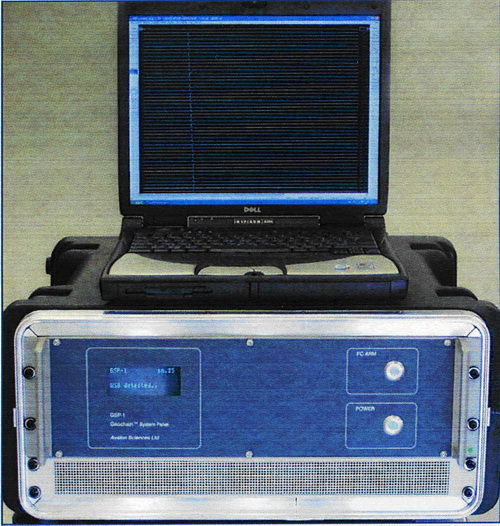
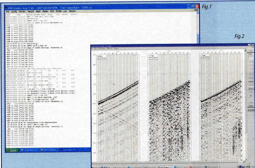
Surface Equipment GSP-1 VSP Data Acquistion System
|
• Up to 16 analogue channels • 512 Kb digital interface • 24bit Delta-Sigma convertors • Built in firing circuit • Full instrument tests • USP interface • Use standard PC running VSProwess software Specifications Analogue section |
 |
Digital section
General
|
|
Functionality
Communication with the PC recording system is by
The GSP incorporates a single airgun firing circuit for use on simple checkshot surveys. For independent external control circuits give control over external source controllers such as our own RSS four gun remote gun firing system
|
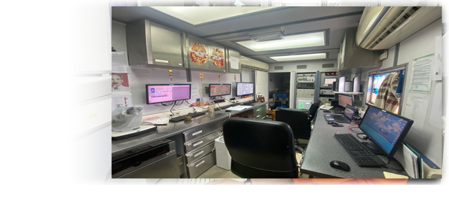
The GSP-1 in use with a Dual analogue system |
| The panel provides fully automatic DC offset and gain calibration along with full instrument tests. The I-test reports are generated on the PC for archiving or for passing on to the client.
Fig1: Acquisition Observer Log Fig2: Stack plot of vertical and horizontal components. |
Nhóm Marketing
Toolpusher Features
|
Features: - Toolpusher is a tool transport system use to convey the logging tools to the bottom of the well, when e-line can not get the tools to T.D. - In many instances experience has proven that much less rig time is used, if Toolpusher is utilized first. - Depending on depth, Toolpusher operations consume about 3 to 4 time more time than e-line conveyed operations. - Any e-line service can be provided via Toolpusher.
|
Nhóm Marketing
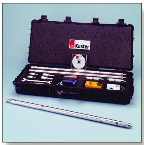
Downhole Pressure And Temperature Equipments
|
K10 “Quazrtz” The K10 “Quartz” is a slick line, E-line , or coiled tubing conveyed downhole memory gauge with significantly enhanced capabilities. In the basic configuration it is a low-cost, hight realiability pressure and temperature recorder. With enhanced feature, it is a low-cost, instrument producing pressure, temperature, and flor along with depth data for a more complete well survey. Features • Entire designed, manufactured and assembled in U.S.A. • “Quartzdyne” quartz resonator transducer • Battery management system within sofware • Buit-in Surface Readout (SRO) mode • Delta P/Delta T sampling options • Redundant memory • Low power requirement • USB interface for fast downloading • Depth data with sireal encoder for Pressure/Time vs. Depth/Time • Upgradeable Firmware • Optional Flowmeter Application • Static and flowing gradient tests • Downhole leak detection • Detecting flowing zones • Injection testing • Gas lifting optimization • Drillstem testing
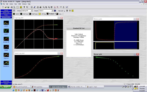
IV. DATA INTERPRETATION At present, VSP well testing team uses Ecrin sofware includes modules for Pressure Transient Analysis (Saphir) and Production Analysis (Topaze).. This software can calculate reservoir parameters as Pi - initial pressure, K - permeability, C - well bore storage, S - skin, R - effect radius, Kh – Perm thickness product, etc. with high accuracy and reliability. It can interpret testing data on oil, gas, water well with different geologic models.
|

Nhóm Marketing
RTTS Safety Joint
|
RTTS Safety Joint The RTTS safety joint is an optional emergency backoff device. The safety joint releases the workstring and tools above the packer if the packer becomes stuck during operations.The design of the RTTS safety joint makes unintentional operation difficult. Features and Benefits • Positive sequence of operation helps prevent premature release. • Tools above it can be retrieved when string is stuck Operation The RTTS safety joint is run immediately above the RTTS packer so that the greatest number of tools above the packer can be removed.Before the safety joint can be used, a tension sleeve located on the bottom of the lug mandrel must first be parted by pulling up on the workstring.After the tension sleeve has parted, the safety joint is released by right-hand torque while the workstring is rotated a specified number of cycles.
RTTS Safety Joint
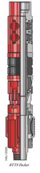
These are the most common sizes. Other sizes may be available. **The values of tensile, burst, and collapse strength are calculated with new tool conditions, Lame’s formula for burst and collapse strength, and stress area calculations for tensile strength. These ratings are guidelines only. For more information, consult your local Halliburton representative. RTTS Packer The RTTS packer is a full-opening, hookwall packer used for testing, treating, and squeeze cementing operations. In most cases, the tool runs with a circulating valve assembly.The packer body includes a J-slot mechanism, mech anical slips, packer elements, and hydraulic slips. Large, heavy-duty slips in the hydraulic holddown mechanism help prevent the tool from being pumped up the hole. Drag springs operate the J-slot mechanism on ≤ 3 1/2-in. (88.9-mm) packer bodies, while larger packer sizes ≥ 4-in. (101.6 mm) use drag blocks. Automatic J-slot sleeves are standard equipment on all packer bodies. The circulating valve, if used, is a locked-open/locked-closed type that serves as both a circulating valve and bypass. The valve automatically locks in the closed position when the packer sets. During testing or squeezing operations, the lock prevents the valve from being pumped open. A straight J-slot in the locked-open position matches with a straightJ-slot (optional) in the packer body. This combination eliminates the need to turn the tubing to close the circulating valve or reset the packer after the tubing has been displaced with cement. Features and Benefits • The full-opening design of the packer mandrel bore allows large volumes of fluid to pump through the tool. Tubing-type guns and other wireline tools can be run through the packer. • The packer can be set and relocated as many times as necessary with simple tubing manipulation. • Tungsten carbide slips provide greater holding ability and improved wear resistance in high-strength casing. Pressure through the tubing activates the slips in the hydraulic holddown mechanism. • An optional integral circulating valve locks into open or closed position during squeezing or treating operations, and opens easily to allow circulation above the packer. Operation The tool is run slightly below the desired setting position to set the packer and is then picked up and rotated several turns. If the tool is on the bottom, only a half-turn is actually required. However, in deep or deviated holes, several turns with the rotary may be necessary. To maintain position, theright-hand torque must be held until the mechanical slips on the tool are set and can start taking weight.The pressure must be equalized across the packer to unset it. As the tubing is picked up, the circulating valve remains closed, establishing reverse circulation around the lower end of the packer. The circulating valve is opened for coming out of the hole when the tubing is lowered, rotated to the right, and picked up. RTTS Packer
|

Nhóm Marketing
FUL-FLO® Hydraulic Circulating Valve
|
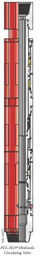
FUL-FLO® Hydraulic Circulating Valve The FUL-FLO® hydraulic circulating valve serves as a bypass around the packer or as a circulating valve to circulate a well after testing.When run below a closed valve, the tool serves as a bypas s around the packer and helps relieve pressure buildup below the closed valve when it is stung into a production packer.When run above a closed valve, the tool can be used as a circulating valve when the workstring is picked up. Features and Benefits • Permits passage of wireline tools through its full-opening bore • Requires no pipe rotation to operate Operation Bypass ports close when weight is set down and reopen when weight is lifted.A hydraulic metering system provides a 2 to 3-minute delay in closing after weight is applied. This delay allows either the RTTS packer to be set or the test string to be stung into a permanent packer before the bypass ports close. The ports reopen without a time delay.During stimulation work, the latching piston adds a downward force on the circulating sleeve to help keep the valve closed.Operation of the valve is the same whether it is used as a circulating valve or as a bypass. No torque is required. Weight is applied to close the tool, and the workstring is picked up to reopen it.
FUL-FLO Hydraulic Circulating Valve
Meets NACE-0175 > 175°F (79°C) standards for H2S service *Service temperature up to 450°F (dressed with 600 series o-rings and PEEK™ back-up seals) **The values of tensile, burst, and collapse strength are calculated with new tool conditions, Lame’s formula for burst and collapse strength, and stress area calculations for tensile strength. ***Pressure rating is defined as differential pressure at the tool. (Differential pressure is the difference in pressure between the casing annulus tool ID.) These ratings are guidelines only. For more information, contact your local Halliburton representative. PEEK is a trademark of ICI Americas, Inc. Poly-Ether-Ether-Ketone. |
Nhóm Marketing