L&TD
LOGGING & TESTING DIVISION
Electrical Micro-Imager
|
EMI – COST-EFFECTIVE TECHNOLOGY FOR FORMATION AND RESEVOIR EVALUATION |
 |
Tool specification
|
| In today’s economically-sensitive energy world, thorough and cost-effective reservoir evaluation is more important than ever before. Halliburton’s Electrical Micro Imaging (EMI™) service is a new process designed to meet these needs by producing core-like electrical micro-conductivity images of the formation sequence encountered in the wellbore.
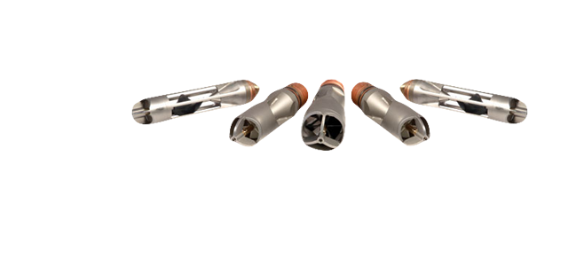
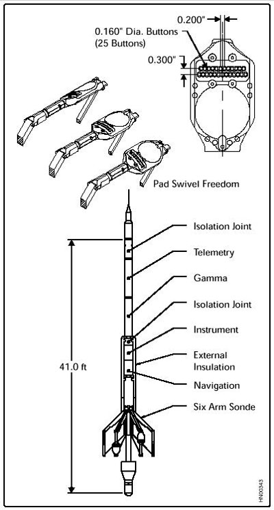
Based on the Award-Winning Six-Arm Dipmeter (SED ™) Technology. The mechanically proven architecture of the EMI is based on six articulating pads, each mounted on an independent arm, allowing improved electrode-to-formation contact. Quality formation images are achieved using 150 pad-mounted sensors distributed 25 on each of the six pads. This results in a measurement resolution of 0.2 inches. Conventional dipmeter information is recorded in addition to the image data. Operating Principles The EMI tool provides an image of the borehole wall by measuring and mapping formation micro-conductivity with the pad-mounted button electrodes. Current is emitted from the lower section of the tool into the formation. Part of this current (survey current) flows from the pad-mounted buttons, but the rest (focusing current) is used for focusing and maintaining high-resolution measurement. The current of each button is recorded as a curve, sampled at 0.1 inch (0.25 centimeters), or 120 samples per foot. The curves reflect the relative micro-conductivity variations within the formation. These current variations are converted to synthetic color or gray-scaled images. Light colors represent low micro-conductivity, while dark colors reflect high micro-conductivity zones. Centralization above and below the EMI mandrel optimizes the distribution of the six pads across the circumference of the borehole, especially in horizontal and highly deviated wells. A full navigation package, consisting of three orthogonal fluxgate accelerometers and three orthogonal magnetometers, is included in the EMI tool to provide accurate information on tool position, motion, direction, and orientation within the borehole. The enormous amount of data acquired while logging is transmitted digitally to the surface unit via Halliburton’s proven Digital Interactive Telemetry System (DITS). |
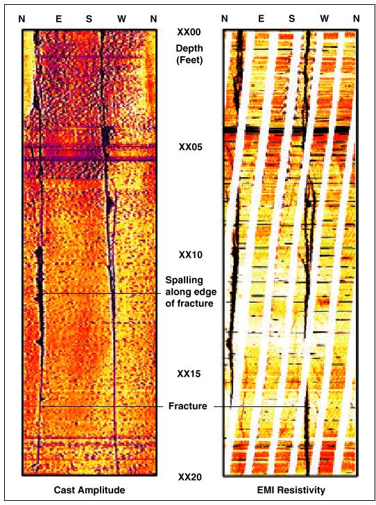
| IMAGING – THE KEY TO BETTER ANALISYS
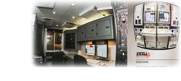
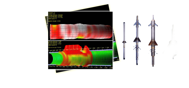
Real-time images are produced at the wellsite. Detailed post-acquisition analysis of the image data is made with high-performance InterView ™ analysis software. Image analysis and enhancement techniques are available for precise identification of formation reservoir characteristics, including the following. |
|
 |
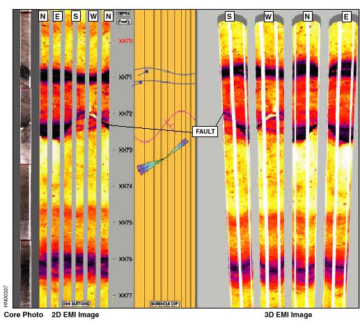
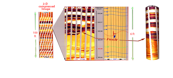
Comparison of EMI image and fullbore core, showing abrupt fault with no associated drag. |
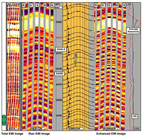 |
Thin bed response of the EMI tool in a laminated sand/shale sequence. |
Nhóm Marketing